Long Spacing Sonic Tool (LSS*)
Description
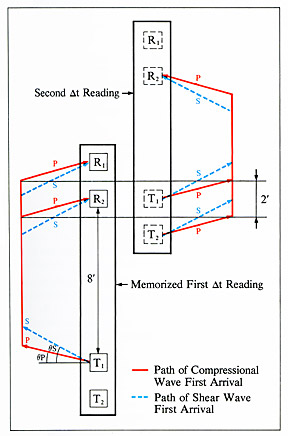 Long Spacing Sonic Sonde (LSS*) contained two acoustic sources spaced two feet apart located eight feet below a pair of receivers also spaced two feet apart. This provided source-receiver offsets of 8, 10, 10, and 12 feet. The measurement relied on the “depth-derived” borehole compensation principle. Compensation was achieved by memorizing the first Δt reading and combining it with a second Δt reading measured after the sonde had been pulled the appropriate distance along the borehole. The symmetry of the sources and receivers allowed travel-time measurements for 8 combinations of sources and receivers. Four of these were reversed by source-receiver reciprocity.
The LSS was used during the Deep Sea Drilling Project from 1981 to 1983 and the Ocean Drilling Program from 1985 to 2003.
Applications
Porosity and “pseudodensity” log. The sonic transit time can be used to compute porosity by using the appropriate transform, and to estimate fracture porosity in carbonatic rocks. In addition, it can be used to compute a “pseudodensity” log over sections where this log has not been recorded or the response was not satisfactory.
Seismic impedance. The product of compressional velocity and density is useful in computing synthetic seismograms for time-depth ties of seismic reflectors.
Sonic waveform analysis. If a refracted shear arrival is present, its velocity can be computed from the full waveforms, and the frequency content and energy of both compressional and shear arrivals can also be determined.
Environmental Effects
One common problem is cycle skipping: a low signal level, such as that occurring in large holes and soft formations, can cause the far detectors to trigger on the second or later arrivals, causing the recorded Δt to be too high. This problem can also be related to the presence of fractures.
Transit time stretching appears when the detection at the further detector occurs later because of a weak signal. Finally, noise peaks are caused by triggering of detectors by mechanically induced noise, which causes the Δt to be too low.
Log Presentation
Delay times (µsec/ft) were usually displayed along with gamma ray and resistivity data.
Tool Specifications
| Temperature rating: | 350° F (175° C) |
| Pressure rating: | 20 kpsi (138 MPa) |
| Diameter: | 3.625 in (9.21 cm) |
| Sampling interval: | 6 in (15.2 cm) |
Major Outputs
| DT: | Short spacing delay time (µsec/ft) |
| DTL: | Long spacing delay time (µsec) |
| TT1: | Transit time 1 (10 ft) (µsec) |
| TT2: | Transit time 2 (8 ft) (µsec) |
| TT3: | Transit time 3 (12 ft) (µsec) |
| TT4: | Transit time 4 (10 ft) (µsec) |
Deployment Notes
The LSS was run alone or in combination with resistivity and gamma ray tools.
* ®trademark of Schlumberger